Pumapeople: Digital Guide Fitting - Pumapeople

Jump to content

  • 2 Pages +
  • 1
  • 2
  • You cannot start a new topic
  • You cannot reply to this topic

Digital Guide Fitting This on my RS2000 but will work for Puma's

#1 User is offline   trev27 

  • Group: Members
  • Posts: 40
  • Joined: 29-January 09
  • Location:Stockton on Tees

Posted 22 February 2009 - 07:27 PM

First of all you need

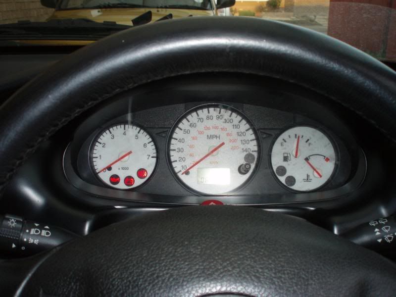
Digital dial and multiplug from a MK4/5 Fiesta, Puma or later Escort


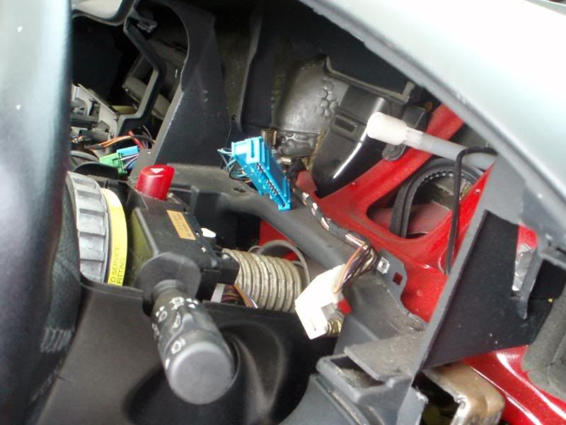
You then need to remove the dash binnicle, original dials.
(see my other guide) Then wire these 2 plugs.....


White plug

1 : Violet – Positive(Switched)
2 : Empty – Low Fuel Warning
3 : Empty - Low Washers Warning
4 : Black/Green – Glow Plug??
5 : Black - Earth
6 : White – Fuel Level
7 : White/Green – Water Temperature
8 : Black/Yellow - Handbrake
9 : 1 Black/Red wire & 1 Black/Green wire - ABS
10 : 2 Black wires - Earth
11 : Violet/White – Main Beam
12 : Orange/Blue - Illumination

Blue Plug

1 : Blue/Black – Indicator (left)
2 : Blue/Green – Indicator (right)
3 : Black/Yellow - Door Ajar Warning
4 : Black/Green – Traction Control Warning
5 : Empty - ??
6 : Black/Green – (Switched Positive)(Goes down to number 12 on BLUE plug)
7 : Blue - Alternator
8 : White/Black - Tachometer
9 : Black/Red - Airbag
10 :White/Green – Oil Warning
11 : Empty - ??
12 : Empty - Positive (Switched??)(Linked from No12 on WHITE plug)


.....to this plug which goes into the back of your new dials


Digi Plug


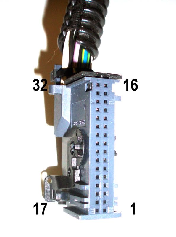
1 permanent 12v (taken from elsewhere as its not in the blue or white plugs)
2 12v switched (on the plugs, linked to pin 22)
3 spare
4 spare
5 spare
6 spare
7 left indicator
8 illumination
9 system monitor (wire to ground)
10 alternator
11 oil indicator
12 handbrake
13 ABS
14 spare
15 spare
16 air bag
17 ground
18 vehicle speed sensor (taken from cable in ecu)
19 spare
20 spare
21 tachometer
22 12v switched (linked to pin 2)
23 fuel s/com (wire to ground)
24 fuel ref (fuel guage)
25 water temperature
26 ground (low wash)
27 ground
28 ground
29 right indicator
30 full beam
31 Door open
32 spare

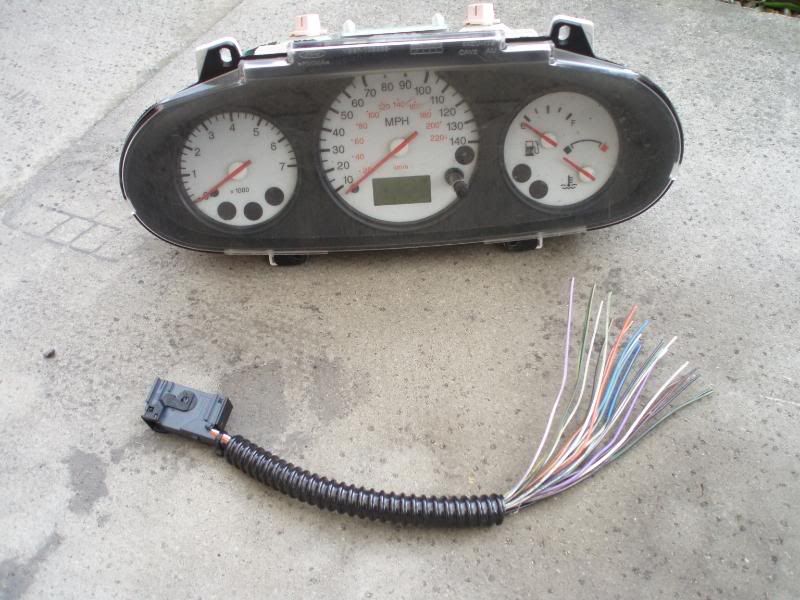
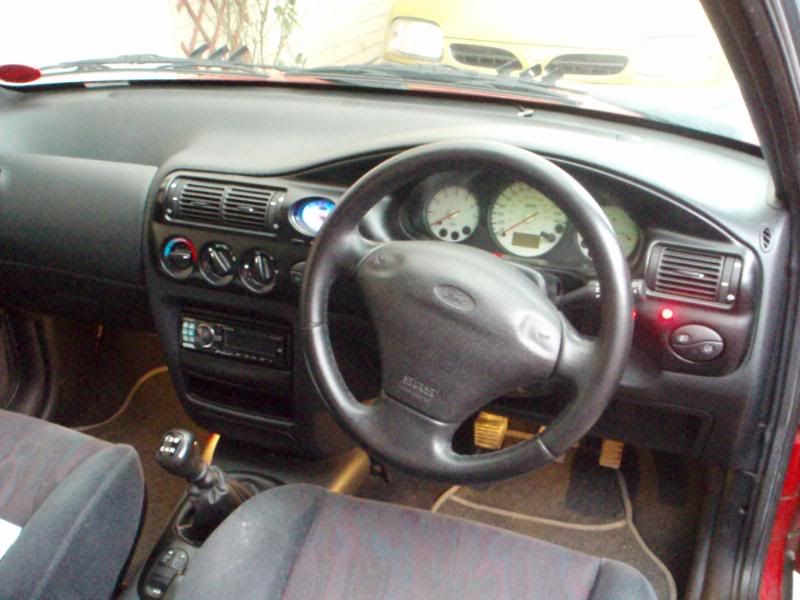
This is what the wires on mine looked like


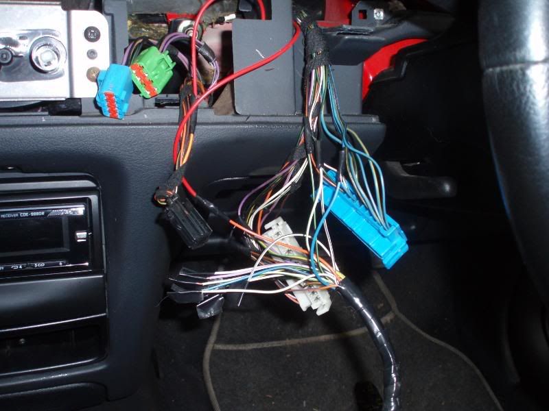
I used the perm live feed from the clock, and spliced into the original wires without cutting the plugs of (just in case
it did n't work), then it can go back to standard dials if needed.


If there are different colours to the wires just just count down
from the blue and white plugs 1 - 12, to find the wire that you need.


Just take your time and double check all wires before connecting.
I did it by first connecting the Perm live, switched live and then
the grounds, then adding one wire at a time i.e handbrake, then turning
on the ignition and seeing if it lit up, after that move on to the next wire, untill they are all done. Then just fit everything back
together and double check that everything works.


The speedo cable will now be useless because the speedometer on
these dials is electrical and takes a feed from the ECU. So you will
need to find out where it is on your ECU. On the RS2000 mk6 (my car)
its on pin 3 on the ECU. The ECU can be found in the front passenger
side footwell, one screw to take off on one side and the other a snap
on fit. Release the single screw securing the ECU and it just pops out.


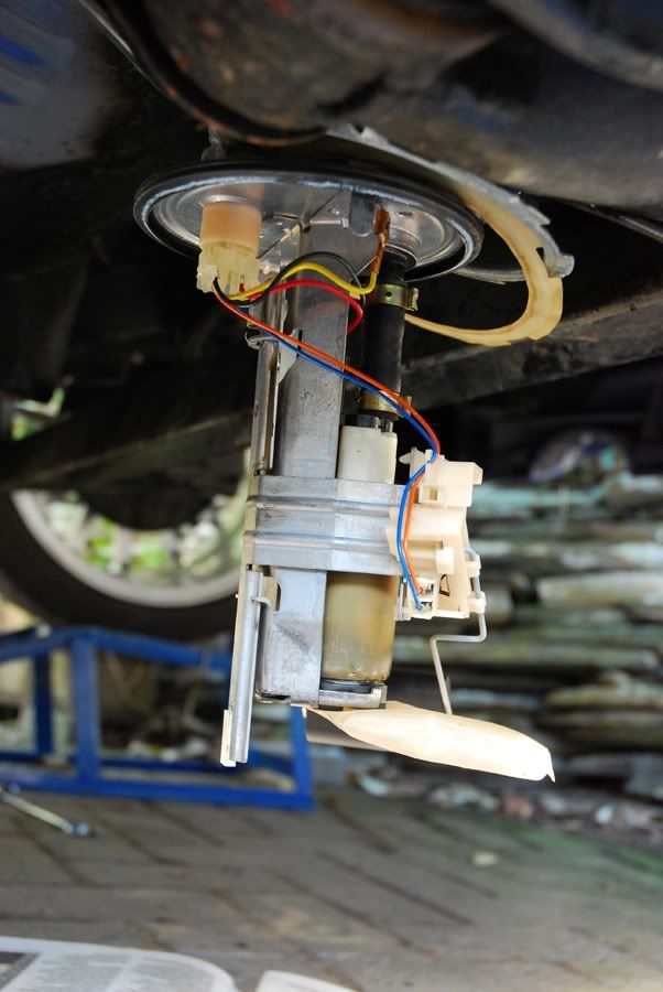
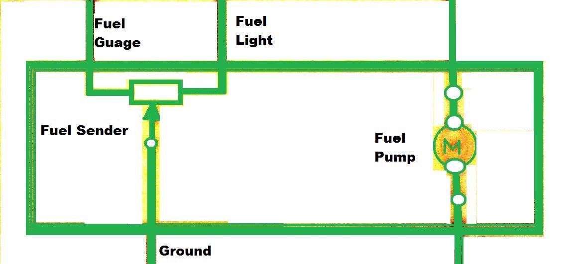
The fuel pump will need to be removed and the wires switched over that are near/on the float, otherwise the fuel gauge will read in reverse.
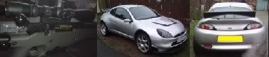
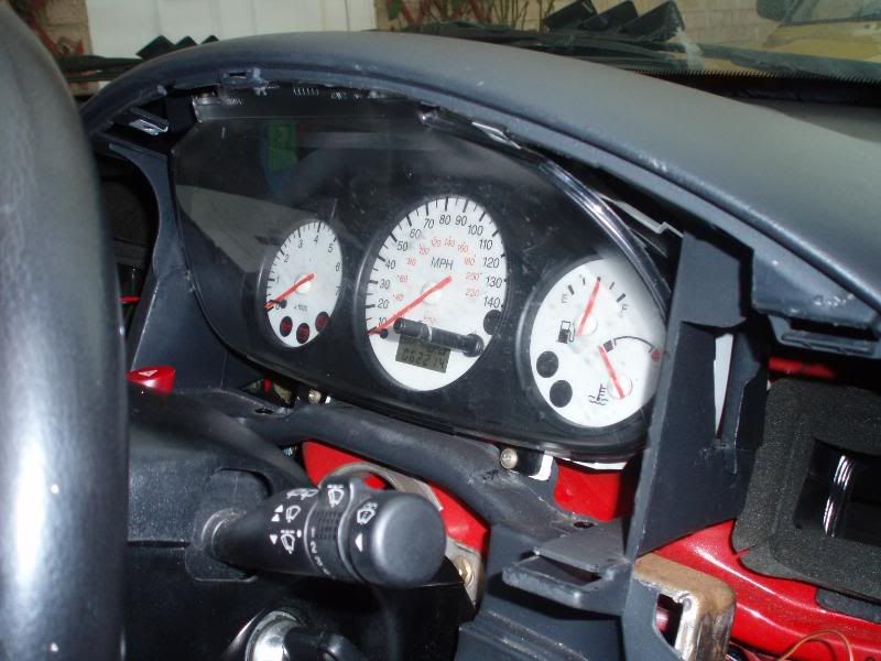
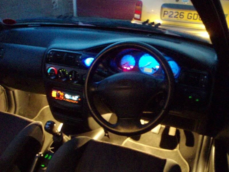
Finished job


Self Diagnostics Mode

The Self Diagnostics Mode gives you in-depth information about your engine and the actual numbers in digital. To use it, follow the steps:

* Insert Key but do not turn it on
* Press and hold the Trip Meter Reset Button
* While holding the reset button, start your car and continue holding the button
* Within 10 seconds, the display should change to "test" in LCD font and the needles will do a full sweeping. Release the Button

Pressing the button will now cycle through some 17 different modes

* 1.Shows a Gauge Sweep
* 2. Shows all 8's on the LCD (LCD TEST)
* 3. Illuminates all the bulbs on the dash
* 4. Displays hexadecimal value for ROM level
* 5. Displays the hexadecimal value for EE level
* 6. Shows DTC (Diagnostic Trouble Code)
* 7. Digital Speedometer - mph
* 8. Digital Speedometer - kph
* 9. N/A
* 10. Digital tachometer
* 11.Fuel volume
* 12. Engine coolant temperature
* 13. Battery voltage
* 14. ABS fail
* 15. Electronic brake distribution (EBD) failure
* 16. Illumination
* 17. Crank Sense

Odometer Display

Description
GAGE Activates gauge sweep of all gauges, then displays present gauge values. Also carries out the checksum tests on ROM and EE. If the gauge sweep is inoperative, INSTALL a new instrument cluster.
All segments illuminated Illuminates all odometer segments. If any odometer segment is inoperative INSTALL a new instrument cluster.
bulb Illuminates all micro-controlled indicators and LEDs. Install a new indicator or LED as necessary.
r Returns to normal operation of all micro-controlled indicators and LEDs and displays hexadecimal value for ROM level. (used when requesting assistance from the hotline). If alternating flashes for FAIL and ROM level are displayed, INSTALL a new instrument cluster.
EE Displays the hexadecimal value for EE level (used when requesting assistance from hotline). If alternating flashes of FAIL and EE level are displayed replace instrument cluster.
dt Displays hexadecimal coding of final manufacturing test date (used when requesting assistance from hotline).
dtc Displays continuous DTC's in hexadecimal format. Pressing the SELECT/RESET button will display any DTCs stored before proceeding to the next step. See index below for description of trouble codes.
enG Displays the English speed in MPH. Speedometer will indicate present speed within tolerances. Display will show 0 if input in not received. If input is invalid for one second or more, or if speed is 0.
m Displays the metric speed data in kph. Speedometer will indicate present speed within tolerances. Display will show 0 if input in not received. If input is invalid for one second or more, or if speed is 0.
tAc Displays the tachometer data received from the PCM via the SCP network within tolerances. Tachometer will indicate present RPM. Display will show 0 if input is no received, if input received is invalid for one second or more, or if engine RPM is 0.
FUEL Displays the code (0-255) for the fuel sender input to the HEC. The fuel gauge will display a filtered fuel level value. This filter will keep the pointer from moving suddenly or erratically.
255 open send +/- 0
232 full stop +/- 0
215 Full mark +/- 10
178 3/4 mark +/- 8
138 1/2 mark +/- 7
93 1/4 mark +/- 5
41 E mark +/- 4
54 Low Fuel (0-59)
0-18 short (0-20 max)
OIL Displays the code (0-250) for the oil pressure switch input to the HEC. Oil pressure gauge will indicate present oil pressure. Normal oil pressure (greater than 6psi) will display a value between 000 and 176. A low oil pressure or an inoperative engine oil pressure switch (less than 6 psi) will display a value greater than 176.
dEGC Display of engine temperature in Degrees C input from cylinder head temperature sensor.
49 C "C" mark
60 C Normal band start
120 C Normal band end
-40 C No SCP message for 5 seconds
bAtt Displays the code (0-255) for the battery voltage input to the HEC. Battery voltage gauge will indicate present battery voltage.
93-102 6.2-9.1 volts, low voltage
115-124 8.5-10.7 volts, Normal band start
215-225 15.8-18 volts, Norm band end
230-241 16.9-19.1 volts, high voltage
rhEo Displays the present decimal rheostat dimming input, 0-255 (used when requesting assistance from the hotline)
rhi
rhS

rho Not used.
Cr Displays the current RUN/START sense input. Display will show -h for high input with the ignition switch in the START position and -L for low input with the ignition switch in the RUN position.
PA-PE7 not used.
GAGE Repeats the display cycle


Blue LEDs fitted


PLEASE NOTE
I WILL NOT BE LIABLE FOR ANYONE WIRING THEIR
CARS WRONG AND SETTING THEMSELVES OR THEIR
CAR ON FIRE!!!!!!!!!!!!!!!!!!!!!!!!

This post has been edited by trev27: 17 March 2009 - 03:55 PM


#2 User is offline   yippeekiay 

  • Group: Members
  • Posts: 1551
  • Joined: 14-October 08
  • Location:Cleveland, NE England

Posted 22 February 2009 - 10:28 PM

Cracking guide...luckily I have these dial already.

Gotta be one for the wiki.

#3 User is offline   trev27 

  • Group: Members
  • Posts: 40
  • Joined: 29-January 09
  • Location:Stockton on Tees

Posted 22 February 2009 - 10:32 PM

Cheers mate, hopefully it will help someone who wants to do this mod.

Forgot to add

Self Diagnostics Mode

The Self Diagnostics Mode gives you in-depth information about your engine and the actual numbers in digital. To use it, follow the steps:

* Insert Key but do not turn it on
* Press and hold the Trip Meter Reset Button
* While holding the reset button, start your car and continue holding the button
* Within 10 seconds, the display should change to "test" in LCD font and the needles will do a full sweeping. Release the Button

Pressing the button will now cycle through some 17 different modes

* 1.Shows a Gauge Sweep
* 2. Shows all 8's on the LCD (LCD TEST)
* 3. Illuminates all the bulbs on the dash
* 4. Displays hexadecimal value for ROM level
* 5. Displays the hexadecimal value for EE level
* 6. Shows DTC (Diagnostic Trouble Code)
* 7. Digital Speedometer - mph
* 8. Digital Speedometer - kph
* 9. N/A
* 10. Digital tachometer
* 11.Fuel volume
* 12. Engine coolant temperature
* 13. Battery voltage
* 14. ABS fail
* 15. Electronic brake distribution (EBD) failure
* 16. Illumination
* 17. Crank Sense


#4 User is offline   warrenpenalver 

  • Group: Members
  • Posts: 4142
  • Joined: 22-January 04
  • Location:Stoke on Trent

Posted 23 February 2009 - 12:11 AM

I shall check this against the early puma wiring diagrams and post a table of pins so people dont have to individually check each wire manually. Will save people time.

Im using double sided copper board to do this mod as then you can plug the hand made "connectors" into the original plugs making it a totally removable sub loom. Also means those who arent so sure of wiring can do it in the knowledge the original loom is mostly uncut.

Can you not swap the wires inside the car to save removing fuel tank??? I need to go to fords at some stage so i will check ford puma fuel sender codes on MICROCAT to see if they are the same for all pumas. If so you wont need to swap wires.

With the fault codes how have you linked it to the ECU to read the fault codes???
Posted Image


#5 User is offline   trev27 

  • Group: Members
  • Posts: 40
  • Joined: 29-January 09
  • Location:Stockton on Tees

Posted 23 February 2009 - 07:40 AM

I am sure that its the wire inside the tank that needs changing, the one attached to the float, so
the fuel pump will need to be removed.

Also found out that swapping pi 32 and putting it in pin 31 will make the door open light work.
This i will post on here aswell to tell you if it does or does n't work

#6 User is offline   warrenpenalver 

  • Group: Members
  • Posts: 4142
  • Joined: 22-January 04
  • Location:Stoke on Trent

Posted 23 February 2009 - 11:23 AM

Ive checked the 97, 99 1/2 and 2000 1/2 puma wiring diagrams to update your pin charts. Changes in bold and red.

White plug

1 : Violet – Positive(Switched)
2 : Black/Orange – Low Fuel Warning
3 : Black/Red - Low Washers Warning
4 : Not used
5 : Black - Earth
6 : White/Red – Fuel Level
7 : White/Red – Water Temperature
8 : Black/Blue - Handbrake
9 : 2 Black/Red - One to ABS, 1 to Traction control
10 : 2 Black wires - Earth
11 : Violet/White – Main Beam
12 : Orange/Blue - Illumination

Blue Plug

1 : Blue/Black – Indicator (left)
2 : Blue/Yellow – Indicator (right)
3 : Black/Blue - Door Ajar Warning
4 : Black/Red – Traction Control Warning
5 : Black/Orange - Not used
6 : Black/Green – Airbag light
7 : Blue/Black - Alternator
8 : White/Black - Tachometer
9 : Black - ground
10 :Black/Green – Oil Warning
11 : Not used
12 : Not used

Digi Plug

1 Orange - permanent 12v (splice into Clock Pin 6 orange/yellow wire)
2 Violet - 12v switched (connects to white plug pin 1)
3 spare
4 spare
5 spare
6 spare
7 Blue/Black - left indicator
8 Orange/Blue - Microprocessor Switched illumination
9 Grey/violet - system monitor (wire to ground)
10 Blue/Black - alternator
11 Black/green - oil indicator
12 Black/Blue - handbrake
13 Black/Red - ABS
14 spare
15 Black/Red - ABS (2000 1/2 spec onwards)
16 Black/Green - air bag
17 Black/orange - ground
18 White/Blue - vehicle speed sensor (Pin 58 ecu, white/Blue wire)
19 White - ECU - spare
20 White/Black - spare
21 White/black - tachometer feed from ECU
22 Blue/white - 12v switched (splice into Clock Pin 1 Blue wire)
23 Black - fuel s/com (wire to ground)
24 White/Red - fuel sender (fuel guage)
25 Not used
26 Black/orange - Washer low resevoir
27 Black/Orange - ground
28 Black - ground
29 Blue/yellow - right indicator
30 Violet/White - full beam
31 Black/Blue - Alarm Module
32 spare


Posted Image


#7 User is offline   trev27 

  • Group: Members
  • Posts: 40
  • Joined: 29-January 09
  • Location:Stockton on Tees

Posted 23 February 2009 - 11:57 AM

Nice work mate.
Been told that pin 31 is for door open, but my digi plug had no wire on 31, but had a wire on 32. Tried pin 32 any way
and did n't work. Also told that if i take out the wire from 32 and put it in 31 it will work on the door open light.
This i will do at the weekend.

#8 User is offline   warrenpenalver 

  • Group: Members
  • Posts: 4142
  • Joined: 22-January 04
  • Location:Stoke on Trent

Posted 23 February 2009 - 12:04 PM

You have to remember there are often slight variations between models even if using the same type of ECU and dash system. The puma for example has mostly two wiring systems, pre 99 1/2, and post 99 1/2 but there were minor revisions in 2000 1/2. Even the fiesta and puma arent the same!!!!

Does your escort have the variable intermittant wiper stalk??? thats a feature not on puma or fiesta (and will be modded to fit by me soon!!).
Posted Image


#9 User is offline   trev27 

  • Group: Members
  • Posts: 40
  • Joined: 29-January 09
  • Location:Stockton on Tees

Posted 23 February 2009 - 02:05 PM

Yeah, mine has the 6 speed wiper

#10 User is offline   warrenpenalver 

  • Group: Members
  • Posts: 4142
  • Joined: 22-January 04
  • Location:Stoke on Trent

Posted 23 February 2009 - 02:06 PM

QUOTE (trev27 @ Feb 23 2009, 11:57 AM) <{POST_SNAPBACK}>
Been told that pin 31 is for door open, but my digi plug had no wire on 31

pin 31 is door open but fed via the alarm system. the door sensors go into the alarm module and the module feeds a light signal to the dash. Was your dash from a puma or fiesta???
Posted Image


#11 User is offline   trev27 

  • Group: Members
  • Posts: 40
  • Joined: 29-January 09
  • Location:Stockton on Tees

Posted 23 February 2009 - 02:38 PM

QUOTE (warrenpenalver @ Feb 23 2009, 02:06 PM) <{POST_SNAPBACK}>
pin 31 is door open but fed via the alarm system. the door sensors go into the alarm module and the module feeds a light signal to the dash. Was your dash from a puma or fiesta???


Came from a V reg 1.7 Puma


#12 User is offline   warrenpenalver 

  • Group: Members
  • Posts: 4142
  • Joined: 22-January 04
  • Location:Stoke on Trent

Posted 23 February 2009 - 03:34 PM

Is pin 31 on the dash itself present??? and connected at the rear?? some times they fit all the pins and just not connect up the disused ones, sometimes they leave the holes empty.


Oh if you see a 6 position wiper stalk in a scrapyard your way could you PM me as im looking for one to use in my puma! Thanks!
Posted Image


#13 User is offline   trev27 

  • Group: Members
  • Posts: 40
  • Joined: 29-January 09
  • Location:Stockton on Tees

Posted 23 February 2009 - 03:43 PM

All the pins are there mate, just no wire connected to pin 31.
Which light on the dash is for the door open? Is it the one on speedo?
I'll keep an eye for 6 speed switch aswell.

This post has been edited by trev27: 23 February 2009 - 03:46 PM


#14 User is offline   warrenpenalver 

  • Group: Members
  • Posts: 4142
  • Joined: 22-January 04
  • Location:Stoke on Trent

Posted 23 February 2009 - 03:55 PM

but what about pin 31 on the dash unit itself??? if theres no wire or solder track on the actual dash unit then it must be pin 32 or another one which means my ford diagrams are wrong or youve got an "odd" set of clocks and dash.

Take the bulbs out and look behind held up to light, or shine a torch from the front. Cant remember which lamp is which!!

Oh and if you find the wiper switch id be after the relay (red 5 pin with "intermittant" on it) as well laugh.gif
Posted Image


#15 User is offline   trev27 

  • Group: Members
  • Posts: 40
  • Joined: 29-January 09
  • Location:Stockton on Tees

Posted 23 February 2009 - 04:20 PM

The dials were from a Puma and the plug from a later Escort. That might explain
the difference in wires to what you have.

#16 User is offline   warrenpenalver 

  • Group: Members
  • Posts: 4142
  • Joined: 22-January 04
  • Location:Stoke on Trent

Posted 23 February 2009 - 04:23 PM

Your probably right there!! that would likely explain your problem. Might also explain the fuel gauge issue too.
Posted Image


#17 User is offline   trev27 

  • Group: Members
  • Posts: 40
  • Joined: 29-January 09
  • Location:Stockton on Tees

Posted 23 February 2009 - 04:37 PM

The problem is definately with the sender and not the plug/dials. Lots of people have done this
conversion to escorts and they all change the sender/swap the wires over to get the fuel gauge to
read correctly.

#18 User is offline   warrenpenalver 

  • Group: Members
  • Posts: 4142
  • Joined: 22-January 04
  • Location:Stoke on Trent

Posted 23 February 2009 - 06:06 PM

I dont think this is a puma issue. this is big boy al's fuel pump/sender: (FRP hence 99 1/2 wiring and digi dash).


There are clearly 5 wires. The pre 99 1/2 diagrams show 5 wires for the fuel unit, the post 99 1/2 use only 4 wires (the fuel light wire is redundant as the dash microprocessor calculates the light from the guage input).

Obviously the extra wire in the fuel unit is redundant and its the same unit as fitted to early puma. I shall confirm this when i get to frauds one day.

This is what the sender wiring looks like on a pre 99 1/2 puma:


The only difference on a post 99 1/2 puma is that the fuel low level light wire is not used.
Posted Image


#19 User is offline   trev27 

  • Group: Members
  • Posts: 40
  • Joined: 29-January 09
  • Location:Stockton on Tees

Posted 27 February 2009 - 12:28 PM

Just got some blue LED's. so will remove the green strip and replace with these LED's.
Nicer than green IMO

#20 User is offline   trev27 

  • Group: Members
  • Posts: 40
  • Joined: 29-January 09
  • Location:Stockton on Tees

Posted 17 March 2009 - 03:56 PM

Updated the first post.

This post has been edited by trev27: 17 March 2009 - 03:56 PM


Share this topic:


  • 2 Pages +
  • 1
  • 2
  • You cannot start a new topic
  • You cannot reply to this topic